


Test A: How stable is the ROV when operating in a strong current
Benchmark: What level of control is there when performing a task in a strong current
Setup: The DVL was mounted to a ROV which was submerged in a water tank. The water tank dimensions were 210x110cm. A camera was mounted 2 meter above the ROV, filming and documenting any movements of the ROV. Another camera was mounted at the bottom of the water tank. A Blue Robotics T-200 thruster was mounted on the side of the tank pointing directly towards the ROV. The thruster was used to create currents in the water.
Performing the test: The ROV was set in “station keep” mode. Altitude was ~5 cm. The thruster creating current was set to about 40% power.
Results: The ROV was easy to control while approaching the target to be picked up. The critical moment when the gripper connected to the target was performed in a controlled manner.
Test B: Station keeping drift
Benchmark: Measurements taken to quantify drift over a set time.
Setup: The DVL was mounted to a Deep Trekker PIVOT ROV which was submerged in a water tank. The water tank dimensions were 210x110cm. A camera was mounted 2 meters above the ROV, filming and documenting any movements of the ROV.
Performing the test: The ROV was set in “station keep” mode. Altitude was ~40 cm. The DVL was usd to provide station keeping for 30 minutes.
Results: The variation between starting position and end position was measured to be less than 1cm.
Test C: Station keeping in a strong current
Benchmark: Visual observation of ability to maintain position while in strong current.
Setup: The DVL was mounted to a ROV which was submerged in a water tank. The water tank dimensions were 210x110cm. A camera was mounted 2 meter above the ROV, filming and documenting any movements of the ROV. Another camera was mounted at the bottom of the water tank. A Blue Robotics T-200 thruster was mounted on the side of the tank pointing directly towards the ROV. The thruster was used to create currents in the water.
Performing the test: The ROV was set in “station keep” mode. Altitude was ~5 cm. The thruster creating current was set to about 40% power.
Results: The ROV was easy to control while approaching the target to be picked up. The critical moment when the gripper connected to the target was performed in a controlled manner.
Test D: Reliable navigation
Benchmark: To establish a benchmark for distance covered an RTK enabled GPS system with 7 mm horizontal accuracy was used.
Setup: Setup: The test was carried out on a boat with the DVL mounted on the bottom of a pole and the RTK GPS system mounted on top of the pole.
Performing the test: The boat was driven 295 meters in a straight line at a speed of 2 knots (~1 meter per second). The DVL altitude from the seabed varied between 4 and 9 meters over the 295 meters route.
Results: The distance measured by the RTK GPS system as 29,569.1 cm and the distance measured by the DVL-A50 was 29,530.6 cm. This 38.5cm difference translates to a distance error of 0.13%.
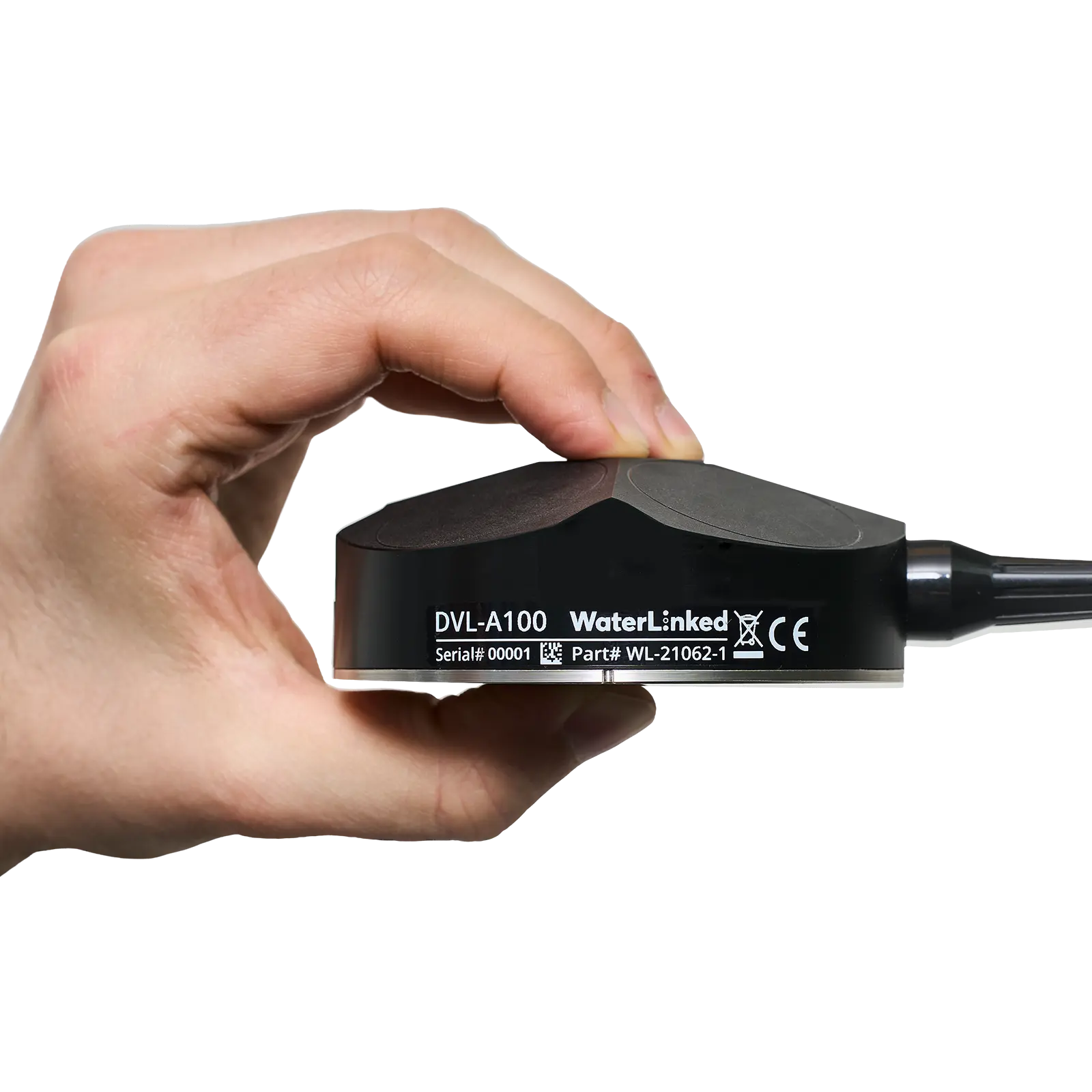 DVL A100
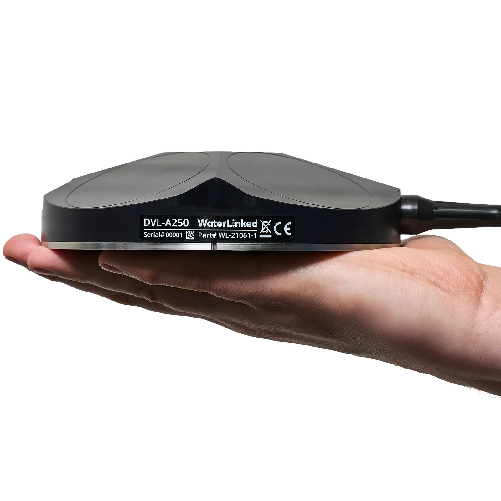 DVL A250